I mentioned using the vestigial connectors a few times in my posts. Explicitly this means I didn't have to disassemble anything inside the battery to connect my charger. If my method of bypassing the circuit hadn't worked then checking the internal circuit would have been my next step.
Signed up just to say thank you to S Keith and everyone else for all the discussions and constant updates on fixing this.
We used the updated vestigial wire charging method. As mentioned, it saves on taking apart the rear part of the battery and having to mess with the relay. You only have to remove the larger cover).
We started to attempt trying the "charge in place" procedure (removing the rear trim, using the slim ratcheting screwdriver, etc) but we were worried about breaking clips. Since we had two people, we just did the battery removal (shown in one of the videos) but basically just 8mm to remove the black AC duct, 13mm for the large bolts, and a 10 mm for the plugs.
For reference to anyone else wondering (as I couldn't tell from the videos), you only need the 30mm security Torx for the top. The pesky side screw that would have required the offset ratcheting screwdriver is a regular 30mm Torx. I only mention it since I already had a "long" 30 mm security Torx and wasn't sure if I needed to buy a short 30mm security Torx as well. All of this is moot, though since we just took out the battery and that removed the need for the offset screwdriver.
2 hrs at 350mA was enough for us to get to 344V, which was enough to start the car. We started with 278V.
Glad it worked out for you. If you haven't already done so, recommend you nab Forscan and run the battery balance routine. This will force charge your battery to about 85% SoC to partially re-balance your cells. Also worth monitoring the "DEL_MOD_V" value in the BCM. This is the single most relevant value for determining if a cell has failed.
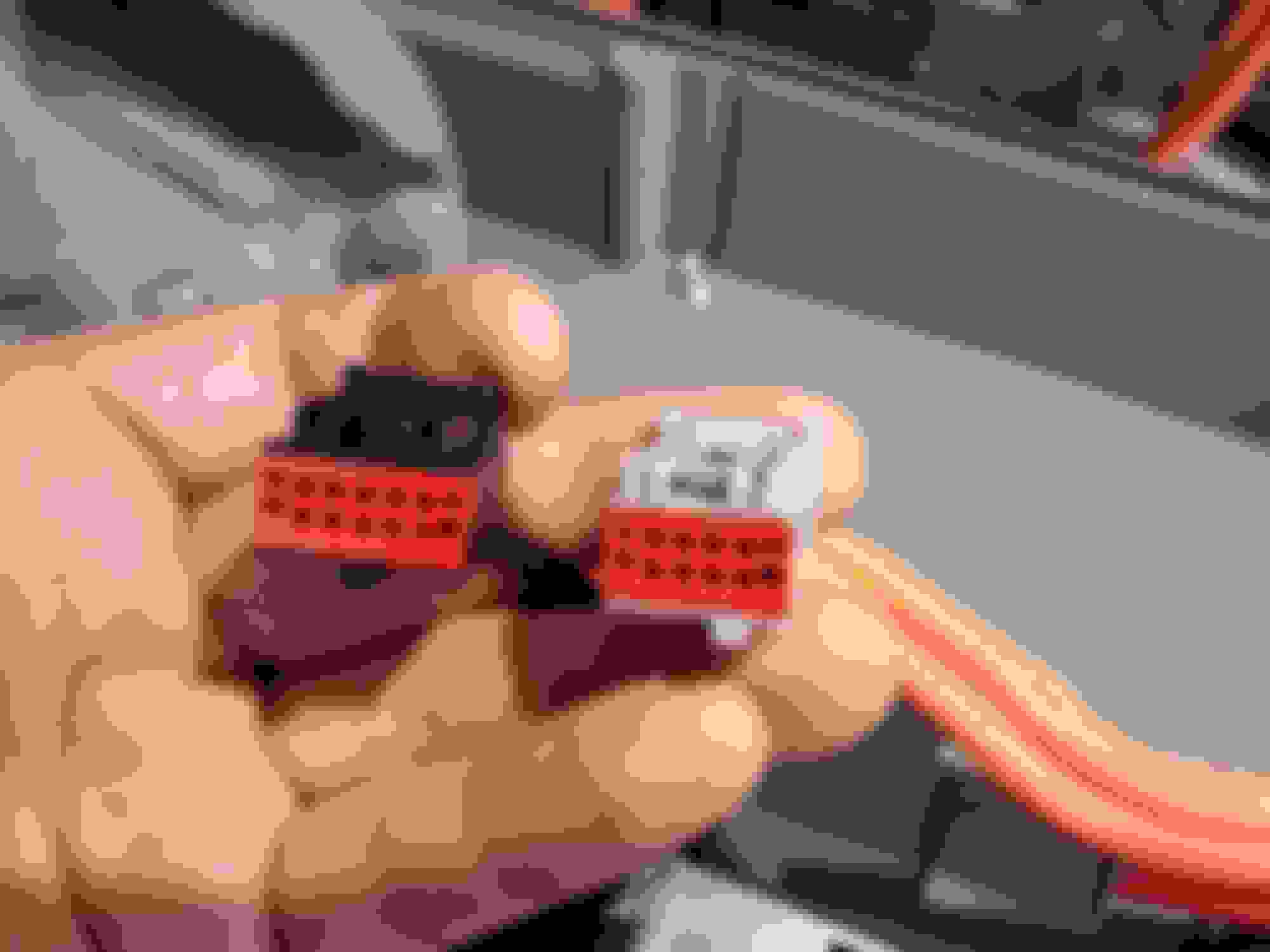
Recently purchased a used battery to recondition and swap out with my old one, thought I'd share some sharper photos of the vestigial connectors. The gray connector is 8-pin, Motorcraft P/N WPT-998. The black connector is 10-pin, WPT-936. I was looking for their counterparts for a plug-n-play approach but can't seem to find them.
Cheers!
Hello all, I am amazed at the amount of helpful information in this thread. My FEH 2009 is sat for a little to long and now recording a low voltage on the High Voltage battery and battery-disabled error codes on FORSCAN. I am planning to use the vestigial charging connectors approach. My challenge will be with building the charger and would appreciate some guidance and someone I can send images back and forth with to ensure I am doing the right thing. If someone can help me, please message me. Thank you guys again!
It probably won't help much, but here's what it looked like when we used the vestigial method. Some wires were soldered together, some were attached with wire nuts. Voltage was monitored throughout the whole charge.
What chargers/LED drivers can you get? If you can afford the wait time, I'd recommend getting the charger mentioned in the first post as it would be safer. I seem to recall both given options maxed out at around 360ish volts which is more inline with battery max voltage.
In our personal case, we ended up using two other power supplies that we could get with a quicker turn around as the person I was helping really needed their car working that week. It really depends what's available near you. The two supplies used outputted 350mA, with max of 200V each (look at the product specs and datasheet of the driver to see). In series, that's 350mA and 400V total. This is not ideal and not something I'd recommend if possible. This is why we monitored the whole time to not accidentally overcharge the battery pack.
The picture is very helpful! Thank you. I ordered the other power source recommended in the thread HLG-120H-350A since that does not require putting two together. It gets here in about two days. I will upload a picture of my setup once I get it going. I also plan to install a pigtail from the vestigial wires for easier charging if this happens again. Did you do that as well?
No, I ended up doing just two test leads (like the kind that come on breadboard jumper wires) put together in the connector hole.
If it happens again, we'd just take it apart again. I think it was Keith who mentioned just leaving the charger inside, and running a extension cord outside. That sounds safer than having any leads connected to the battery output being outside (if that is what you were planning on doing). Extension cord would only be in use if discharge ever happened again, and is isolated from the battery output. Any output/pigtail outside the battery would be energized anytime the safety plug is inserted (basically all the time). Too much risk IMO.
ah I see. I get what you mean. I�ll go with the safer option and route the extension out instead and leave the charger in place of the previous jumpstart from the previous gen.
When you click on links to various merchants on this site and make a purchase, this can result in this site earning a commission. Affiliate programs and affiliations include, but are not limited to, the eBay Partner Network.