Nav System & Bluetooth


Active Enthusiast
Joined: Aug 2006
Posts: 155
From: Vancouver, BC, Canada
I took the NAV radio out today trying to install the Parrot 3200 LS, and I snapped some photos for reference too.
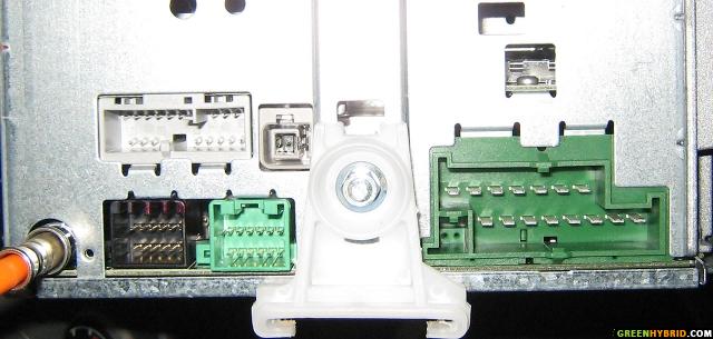
Back of Radio:
Ford Cables/Harness:

By the way, the cables on the Parrot 3200 LS are drastically different from the ones on the Visteon/Parrot 3100 unit that have been discussed previously on this thread. Now I'm studying how 3200 would fit on my NAV Radio, because the diagrams posted earlier on this thread doesn't seem to apply.
Here's a photo of the 3200 Harness:

Back of Radio:
Ford Cables/Harness:
By the way, the cables on the Parrot 3200 LS are drastically different from the ones on the Visteon/Parrot 3100 unit that have been discussed previously on this thread. Now I'm studying how 3200 would fit on my NAV Radio, because the diagrams posted earlier on this thread doesn't seem to apply.
Here's a photo of the 3200 Harness:
Last edited by greenhybrider; Nov 17, 2006 at 01:19 AM.
Active Enthusiast
Joined: Aug 2006
Posts: 155
From: Vancouver, BC, Canada
By the way, there's a site selling Parrot Harness Kits designed for various vehicles:
http://www.parrotkits.com/donotcut.html
I'm already in touch with the seller to determine if one of their harness would work with the FEH NAV Radio without splicing, "vampiring" and connecting extra wires.
http://www.parrotkits.com/donotcut.html
I'm already in touch with the seller to determine if one of their harness would work with the FEH NAV Radio without splicing, "vampiring" and connecting extra wires.
Ridiculously Active Enthusiast
Joined: Jun 2006
Posts: 881
From: Philadelphia, PA
Actually, from the looks of the diagrams installation isn't that different at all. The confusing part is that they don't explain wires 5 and 6 (green and brown) in any of their documentation. I BELIEVE...and maybe mike can confirm this....but it looks to me from the Ford diagram and mike's installation that you DO NOT need to connect the speaker wires b/c the Ford Nav radio has Phone Audio inputs (pins 8 and 9). Therefore you just connect the un-mentioned green wire and brown wire from the Parrot kit to the 8 and 9 pins of the nav/accesory jack as shown in the diagram on page 2 of this thread.
Yellow Mute connects to pin 4 of the accessory/nav jack
Orange, Red and Black power wires connect to pins 3, 1 and 6 of the power jack
It seems MUCH easier and cheaper to install as mike's guys did by "vampire" connections and using pins than buying an adapter kit for $60 but that's just me. 6 wires and your done. Speaking of which, I'm ordering my Parrot kit today I think!!!
Ridiculously Active Enthusiast
Joined: Jun 2006
Posts: 881
From: Philadelphia, PA
All of this makes me wonder something else.....
If the Nav radio has a line-level input for phone devices.....(anyone guess where I am going with this???)....I wonder if one could run a line level output from, say an MP3 player or other such device like a satellite radio, to the line-in and just press the phone button to activate it......hmmmmmmmm
If the Nav radio has a line-level input for phone devices.....(anyone guess where I am going with this???)....I wonder if one could run a line level output from, say an MP3 player or other such device like a satellite radio, to the line-in and just press the phone button to activate it......hmmmmmmmm
Active Enthusiast
Joined: Aug 2006
Posts: 155
From: Vancouver, BC, Canada
Originally Posted by Tim K
The confusing part is that they don't explain wires 5 and 6 (green and brown) in any of their documentation.
Originally Posted by Tim K
Therefore you just connect the un-mentioned green wire and brown wire from the Parrot kit to the 8 and 9 pins of the nav/accesory jack as shown in the diagram on page 2 of this thread.

Originally Posted by Tim K
Yellow Mute connects to pin 4 of the accessory/nav jack

Originally Posted by Tim K
Orange, Red and Black power wires connect to pins 3, 1 and 6 of the power jack

Originally Posted by Tim K
It seems MUCH easier and cheaper to install as mike's guys did by "vampire" connections and using pins than buying an adapter kit for $60 but that's just me. 6 wires and your done. Speaking of which, I'm ordering my Parrot kit today I think!!!

Last edited by greenhybrider; Nov 17, 2006 at 03:32 PM. Reason: clarity
Ridiculously Active Enthusiast
Joined: Jun 2006
Posts: 881
From: Philadelphia, PA
Originally Posted by greenhybrider
If I'm not mistaken, when you look at the Parrot 3200 LS harness photo I posted, the extra "lines" are in red/black and brown/white bundles. There are no green and brown color wires. My first question: assuming the red and brown wires are the correct "lines" to connect to NAV jack, which of the two goes into 8 and which goes into pin 9 on the radio?
I don't see the green and brown wires from the Parrot 3200 Harness, unfortunately Parrot's manual/guide doesn't explain what these brown/white, red/black lines too either
I don't see the green and brown wires from the Parrot 3200 Harness, unfortunately Parrot's manual/guide doesn't explain what these brown/white, red/black lines too either
Yes I think I can do this myself: attach a female connector to the end of the yellow wire and slide it into the ford NAV accessory jack. Right?!
This part I'm not sure. First question is, which one is the power jack?! Also, is this where I need to attach one of those vampire connectors to tap into the 12V ignition and battery power, like the photo here:
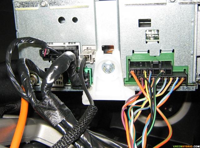
The connector on the top right with 7 slots is the power jack. The Red power wire from the 3200 labelled 12V ignition clips into the thick orange/green wire in pin 1, the Orange wire from the 3200 that I can't read clips into the yellow/black wire in pin 3, the black ground from the 3200 clips into the black/green wire in pin 6....all using the "vampire" connectors.
Ridiculously Active Enthusiast
Joined: Jun 2006
Posts: 881
From: Philadelphia, PA
FYI, I ordered my 3100 on Friday. I should have it sometime this week. I'll make sure to take installation photos and post them when I am done.
$135 delivered, not bad.
$135 delivered, not bad.
Ridiculously Active Enthusiast
Joined: Jul 2006
Posts: 1,197
From: Lehigh Valley, PA
Originally Posted by Tim K
All of this makes me wonder something else.....
If the Nav radio has a line-level input for phone devices.....(anyone guess where I am going with this???)....I wonder if one could run a line level output from, say an MP3 player or other such device like a satellite radio, to the line-in and just press the phone button to activate it......hmmmmmmmm
If the Nav radio has a line-level input for phone devices.....(anyone guess where I am going with this???)....I wonder if one could run a line level output from, say an MP3 player or other such device like a satellite radio, to the line-in and just press the phone button to activate it......hmmmmmmmm
Ridiculously Active Enthusiast
Joined: Jul 2006
Posts: 1,197
From: Lehigh Valley, PA
Originally Posted by greenhybrider
Also, is this where I need to attach one of those vampire connectors to tap into the 12V ignition and battery power, like the photo here:
Active Enthusiast
Joined: Aug 2006
Posts: 155
From: Vancouver, BC, Canada
Originally Posted by Tim K
I can't tell the colors in your photo

Originally Posted by Tim K
but based on the labels and Mike's diagram of his install it would appear that the dark wire from the 3200 labelled Line "-" should be connected to pin 9 of the Ford radio. The light wire labelled Line "+" should be connected to pin 8 of the Ford Radio.
My photo above only shows the stickers for white and brown wires only. The red and black wires also have the "Line -" and "Line +" stickers as well which I have labelled accordingly.
Now I'm confused because Pin 8 and 9 on Ford Jack should only accept one wire each? But when there are 2 wires for each "Line -" and "Line +", how do I choose?!


