Modifying the AC control on an Escape Hybrid
#1
 05-29-2007, 10:22 AM


Intro
As are others of you, I was frustrated at my inability to control the AC on my own. Most
specifically I was annoyed that I couldn't have the defrost on without the AC. I wanted better
control of the air conditioning. So, I set about to change it.
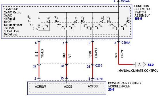
The first step was to learn the operation of the controls. I got the schematic, and determined
the values of the individual control wires. The important part of the schematic are shown below.
The full schematic page can be found at:
http://i34.photobucket.com/albums/d1...ematicFull.jpg
If you study the control schematic, you will see that there are three signals that are routed to
the AC system. They are: ACRSW, ACCS, and ACFDS.
ACRSW is connected (to 12v) when the switch is at: Off, Max AC, AC Recirc. This signal controls
the recirculate ability of the system.
ACCS is connected when the switch is at: AC Recirc, AC. This corresponds to the "green" AC mode
where the engine is not forced on.
ACFDS is connected when the switch is at: Max AC, Def/Floor, Defrost. This corresponds to the AC
mode where the engine is forced to run.
Given this information, I set about creating my AC control. Now it should be noted that you
could simply put a switch on the ACCS and ACFDS control signals, and connect them to 12v. This
would be far easier than what I set about doing. Most of the reason for my extra work is that I
wanted the system to fit without looking out of place.
As are others of you, I was frustrated at my inability to control the AC on my own. Most
specifically I was annoyed that I couldn't have the defrost on without the AC. I wanted better
control of the air conditioning. So, I set about to change it.
The first step was to learn the operation of the controls. I got the schematic, and determined
the values of the individual control wires. The important part of the schematic are shown below.
The full schematic page can be found at:
http://i34.photobucket.com/albums/d1...ematicFull.jpg
If you study the control schematic, you will see that there are three signals that are routed to
the AC system. They are: ACRSW, ACCS, and ACFDS.
ACRSW is connected (to 12v) when the switch is at: Off, Max AC, AC Recirc. This signal controls
the recirculate ability of the system.
ACCS is connected when the switch is at: AC Recirc, AC. This corresponds to the "green" AC mode
where the engine is not forced on.
ACFDS is connected when the switch is at: Max AC, Def/Floor, Defrost. This corresponds to the AC
mode where the engine is forced to run.
Given this information, I set about creating my AC control. Now it should be noted that you
could simply put a switch on the ACCS and ACFDS control signals, and connect them to 12v. This
would be far easier than what I set about doing. Most of the reason for my extra work is that I
wanted the system to fit without looking out of place.
Last edited by salsbr; 05-29-2007 at 10:25 AM.
#2
05-29-2007, 10:23 AM
Switch Modification / Design
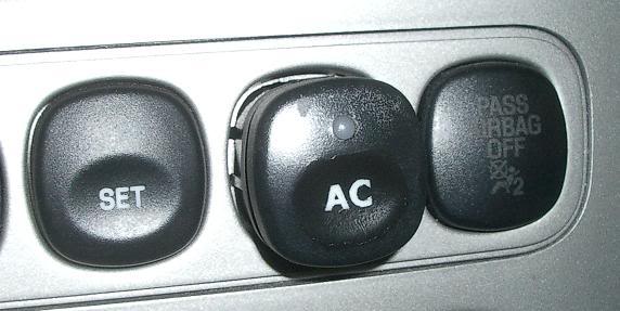
For my control I decided to add a console switch since I had a blank to the right of the SET
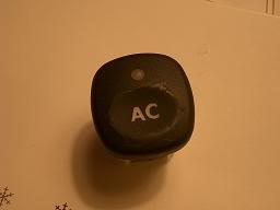
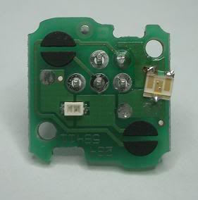
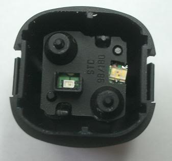
button. To do this I ordered a second rear window defrost button. This was part #
5L8Z-18578-BAA. This part looks like:
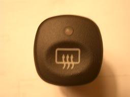
Interestingly, it was not identical to my existing rear window defrost button, but was close
enough so I wasn't worried about it.
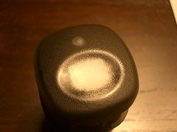
When pulled apart, this switch looks like this:
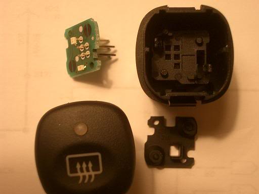
The first thing I did was to set about changing the graphic on the switch. This process envolved
me using rubbing compound to remove the old graphic.
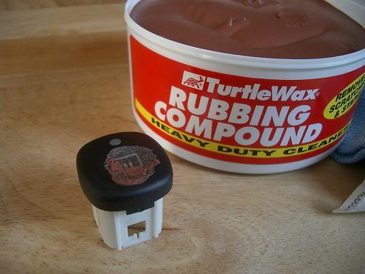
Since it would be tedious and boring to remove this by hand, I attached a q-tip to my drill, and
used it with the rubbing compound to remove the graphic.

The end result was this:
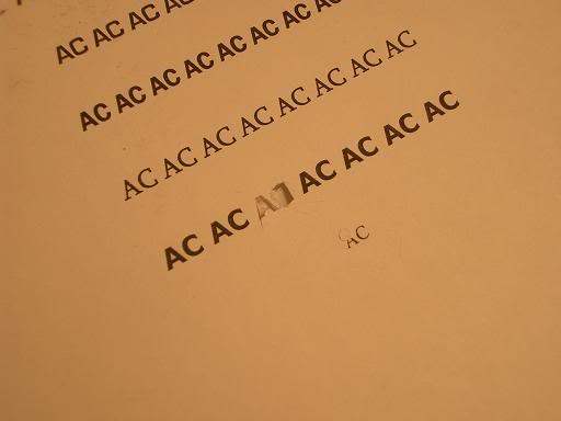
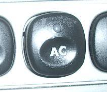
Now I needed to put my graphic onto the switch. I looked at a bunch of options, but decided to
go with the simple "AC" because it was going to be the easiest to apply, and because it would
make sense to anyone. To do this, I printed AC onto a mailing label (in a bunch of different
fonts so I could see which I wanted), and then cut out the AC of my choice.
Next, I applied the sticker to my modified switch, and them sprayed it with matte black paint.
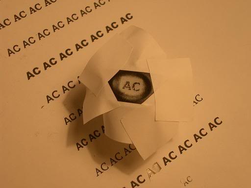
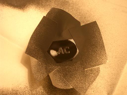
After removing the sticker, it looked like this:
To finish it, I used a little rubbing compound to smooth it out, and then sprayed it with a clear
coat with a matte finish to give it better durability.
Now that I had the switch externally finished, I needed to get my controls designed.
For my control I decided to add a console switch since I had a blank to the right of the SET
button. To do this I ordered a second rear window defrost button. This was part #
5L8Z-18578-BAA. This part looks like:
Interestingly, it was not identical to my existing rear window defrost button, but was close
enough so I wasn't worried about it.
When pulled apart, this switch looks like this:
The first thing I did was to set about changing the graphic on the switch. This process envolved
me using rubbing compound to remove the old graphic.
Since it would be tedious and boring to remove this by hand, I attached a q-tip to my drill, and
used it with the rubbing compound to remove the graphic.
The end result was this:
Now I needed to put my graphic onto the switch. I looked at a bunch of options, but decided to
go with the simple "AC" because it was going to be the easiest to apply, and because it would
make sense to anyone. To do this, I printed AC onto a mailing label (in a bunch of different
fonts so I could see which I wanted), and then cut out the AC of my choice.
Next, I applied the sticker to my modified switch, and them sprayed it with matte black paint.
After removing the sticker, it looked like this:
To finish it, I used a little rubbing compound to smooth it out, and then sprayed it with a clear
coat with a matte finish to give it better durability.
Now that I had the switch externally finished, I needed to get my controls designed.
#3
05-29-2007, 10:23 AM
Circuit Design
I decided I wanted the functionality to be, Press once, and the AC turns on in Green mode. Press
again, and it comes on in normal mode. I wanted the feedback to be a green light for the green
mode, and a red light for the normal mode. Pressing the switch again causes the AC to turn off.
I thought of a number of ways to do this, but settled on the easiest for me. This was to use a
small microprocessor in the circuit. There are certainly other ways to do this, and all I am
doing is switching 12v to the signals ACCS and ACFDS at the appropriate times.
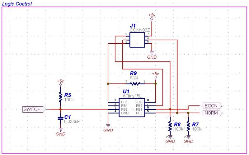
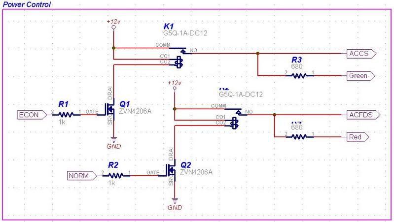
The schematic consists of three parts: The logic control, the power control, and the power
supply. These are shown below.
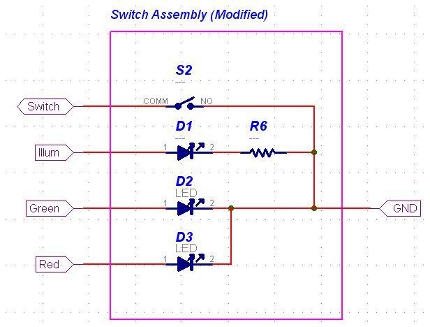
I'll get to what these do in a second, but they also required a modification to the physical
switch. The modified switch schematic is shown next.
Ok, the schematic is fairly simple. In the logic section, the processor (ATtiny15L) simply takes
the switch input, and creates two outputs for ACCS and ACFDS, but are called Econ and Norm at
this point. These signals are used to enable or disable the relays in the Control schematic. It
is the relays that connect 12v to the signals ACCS and ACFDS. Also off of the relay output is
the drive signal for the feedback LEDs.
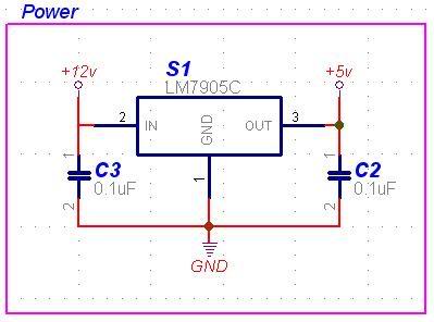
The final portion of the schematic is simply here to provide power for the processor. It
converts 12v into 5v.
The modified switch now has two LEDs (Red and Green) for feedback, but still has the illumination
LED so you can see it when the lights are on at night.
I decided I wanted the functionality to be, Press once, and the AC turns on in Green mode. Press
again, and it comes on in normal mode. I wanted the feedback to be a green light for the green
mode, and a red light for the normal mode. Pressing the switch again causes the AC to turn off.
I thought of a number of ways to do this, but settled on the easiest for me. This was to use a
small microprocessor in the circuit. There are certainly other ways to do this, and all I am
doing is switching 12v to the signals ACCS and ACFDS at the appropriate times.
The schematic consists of three parts: The logic control, the power control, and the power
supply. These are shown below.
I'll get to what these do in a second, but they also required a modification to the physical
switch. The modified switch schematic is shown next.
Ok, the schematic is fairly simple. In the logic section, the processor (ATtiny15L) simply takes
the switch input, and creates two outputs for ACCS and ACFDS, but are called Econ and Norm at
this point. These signals are used to enable or disable the relays in the Control schematic. It
is the relays that connect 12v to the signals ACCS and ACFDS. Also off of the relay output is
the drive signal for the feedback LEDs.
The final portion of the schematic is simply here to provide power for the processor. It
converts 12v into 5v.
The modified switch now has two LEDs (Red and Green) for feedback, but still has the illumination
LED so you can see it when the lights are on at night.
#4
05-29-2007, 10:23 AM
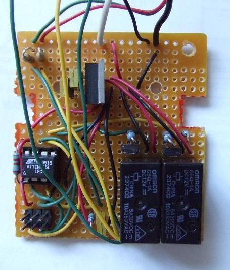
Circuit Build
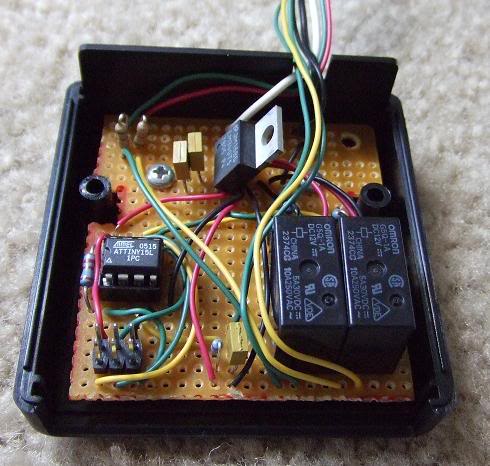
Once complete, the circuit looked like:
The modification of the switch was fairly difficult. Modified it looks like like:
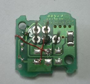
You can imagine that hand soldering SMT parts wasn't the easiest thing ever. But it was required
to get the new Red/Green LED in the only place it could go and still show through the indicator
window.
I put the control circuit into a case.
When enclosed, it looked like this:
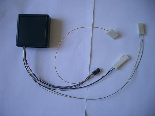
You should note that I used connectors to attach the new control box into the AC system. This is
really because I like being able to remove my modifications. This makes it very easy.
Now it's time for the install.
Once complete, the circuit looked like:
The modification of the switch was fairly difficult. Modified it looks like like:
You can imagine that hand soldering SMT parts wasn't the easiest thing ever. But it was required
to get the new Red/Green LED in the only place it could go and still show through the indicator
window.
I put the control circuit into a case.
When enclosed, it looked like this:
You should note that I used connectors to attach the new control box into the AC system. This is
really because I like being able to remove my modifications. This makes it very easy.
Now it's time for the install.
#5
05-29-2007, 10:24 AM
Install
First, I removed my radio. It is helpful if you put a rag over the gear shifter since it is
helpful to rest the radio on something when unplugging the connectors.
Second, you pull off the center console. This is held on at the four corners, you can feel the
connect points by reaching in through the radio hole. Pressing out on these points made it
easier for me to remove the console. You will also note that I have a cloth below the console.
This will keep you from scratching the plastic below the console.
Removing the blank switch is accomplished by simply pushing on it from the back. It will pop
right out. You should notice that the blank is keyed, and not all switches can fit into this
hole.
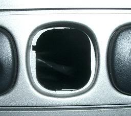
To get my AC switch to fit, I modified the blank spot with an extra keying slot as follows:

Now the switch will slide right in. Don't actually click it in yet as they are much harder to
get out than the blanks.
Now we need to put the connectors onto the various signals. This is mostly splicing into
signals, but you do need to cut a couple of wires and solder some connectors on.
I recommend using your camera liberally so you know how to put everything back in its proper
place. Since I had to disconnect everything from the console, it was a wise move.
First I connected power and ground.
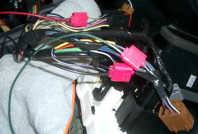
You can see that these are connected to a black wire (GND), and Brown-Yellow for power. The
power wire is hot only when the Climate Control selector is not set to OFF. This wire can be
seen in the partial control schematic of the function selector switch. Using this power ensures
that no power will be put on the ACCS and ACFDS lines when OFF is selected on the control.
Next I spliced into the Cluster Illumination power. This wire is Light Blue-Red on the existing
rear window / defrost switch per the car schematics.
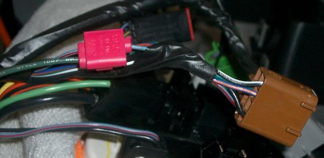
Finally, I had to cut the ACCS and ACFDS lines. In this picture I have cut the wires, and
installed the connector. I also put shrink wrap around any exposed wires.
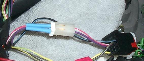
The ACCS wire is Violet, and the ACFDS wire is Pink-White per the schematic.
Also worth noting in this picture is that I have connected the wires back to the original wires.
Like I mentioned earlier, I like being able to back out my changes, so for this mod I simply need
to connect these two wires to the connector.
Now I must mount the control box. I used Velcro Extreme to attach the box to the frame. Fairly
straight forward, and easy to remove.
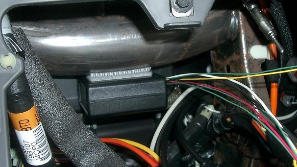
Now it is a matter of connecting the connectors, and putting the center console back together.
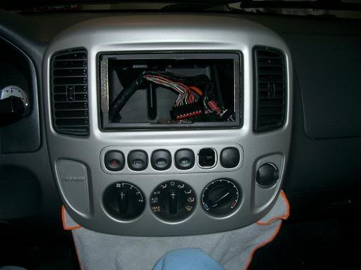
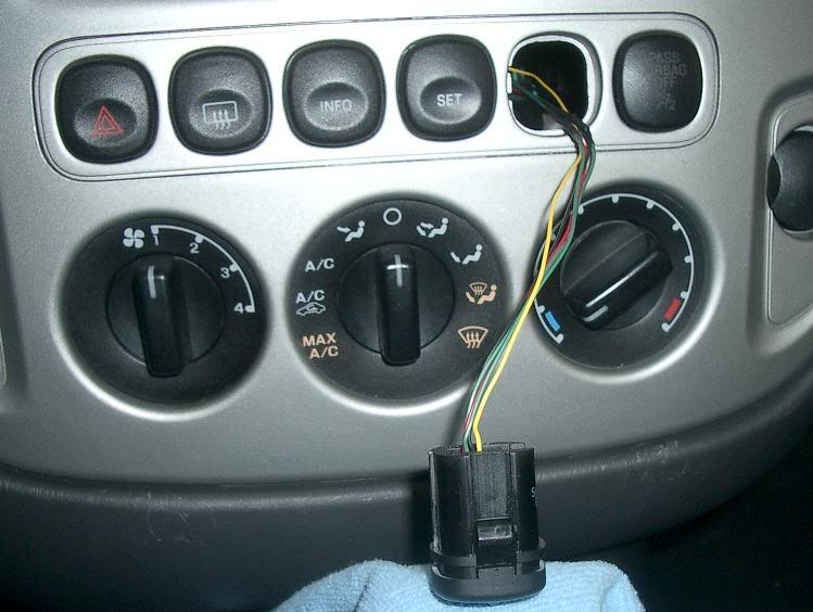
This next picture shows the console back together, and my new switch hanging out. It is
important to have enough wire on this connector since it is harder to connect than the others.

You can see that I didn't take my own advice about protecting the plastic below the console.
They are my scratches of shame.
Then slip the switch back in the hole.
Finally, put the radio back in, and you're done!
First, I removed my radio. It is helpful if you put a rag over the gear shifter since it is
helpful to rest the radio on something when unplugging the connectors.
Second, you pull off the center console. This is held on at the four corners, you can feel the
connect points by reaching in through the radio hole. Pressing out on these points made it
easier for me to remove the console. You will also note that I have a cloth below the console.
This will keep you from scratching the plastic below the console.
Removing the blank switch is accomplished by simply pushing on it from the back. It will pop
right out. You should notice that the blank is keyed, and not all switches can fit into this
hole.
To get my AC switch to fit, I modified the blank spot with an extra keying slot as follows:
Now the switch will slide right in. Don't actually click it in yet as they are much harder to
get out than the blanks.
Now we need to put the connectors onto the various signals. This is mostly splicing into
signals, but you do need to cut a couple of wires and solder some connectors on.
I recommend using your camera liberally so you know how to put everything back in its proper
place. Since I had to disconnect everything from the console, it was a wise move.
First I connected power and ground.
You can see that these are connected to a black wire (GND), and Brown-Yellow for power. The
power wire is hot only when the Climate Control selector is not set to OFF. This wire can be
seen in the partial control schematic of the function selector switch. Using this power ensures
that no power will be put on the ACCS and ACFDS lines when OFF is selected on the control.
Next I spliced into the Cluster Illumination power. This wire is Light Blue-Red on the existing
rear window / defrost switch per the car schematics.
Finally, I had to cut the ACCS and ACFDS lines. In this picture I have cut the wires, and
installed the connector. I also put shrink wrap around any exposed wires.
The ACCS wire is Violet, and the ACFDS wire is Pink-White per the schematic.
Also worth noting in this picture is that I have connected the wires back to the original wires.
Like I mentioned earlier, I like being able to back out my changes, so for this mod I simply need
to connect these two wires to the connector.
Now I must mount the control box. I used Velcro Extreme to attach the box to the frame. Fairly
straight forward, and easy to remove.
Now it is a matter of connecting the connectors, and putting the center console back together.
This next picture shows the console back together, and my new switch hanging out. It is
important to have enough wire on this connector since it is harder to connect than the others.
You can see that I didn't take my own advice about protecting the plastic below the console.
They are my scratches of shame.
Then slip the switch back in the hole.
Finally, put the radio back in, and you're done!
#6
05-29-2007, 10:24 AM
Finished Product
Here are some pics of the finished product.
Economy AC Mode
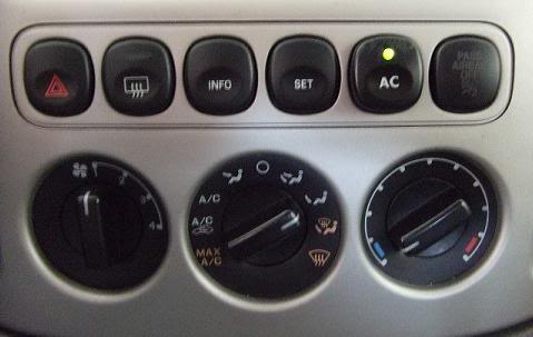
Normal AC Mode
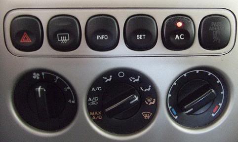
Switch Illumination
I suppose if you read through the entire thing, you will note that I glossed over a few things
(such as the schematic design). If you want to know about something, just ask!
Enjoy,
salsbr
Here are some pics of the finished product.
Economy AC Mode
Normal AC Mode
Switch Illumination
I suppose if you read through the entire thing, you will note that I glossed over a few things
(such as the schematic design). If you want to know about something, just ask!
Enjoy,
salsbr
#7
05-29-2007, 10:52 AM
I hear what you saying, and I agree with it on basic terms, but I have to add that my Honda has a separate button for the A/C compressor. With the A/C compressor off, the windshield defogger is worthless. I can let it run and run and run, with the fan on max, and it will do little to clear off the fog. I press the A/C button 'on', and within like 30 seconds, the windshield clears.
#8
05-29-2007, 11:33 AM
I hear what you saying, and I agree with it on basic terms, but I have to add that my Honda has a separate button for the A/C compressor. With the A/C compressor off, the windshield defogger is worthless. I can let it run and run and run, with the fan on max, and it will do little to clear off the fog. I press the A/C button 'on', and within like 30 seconds, the windshield clears.
My former vehicle was an Acura Integra, and although the windshield definitely cleared quicker with AC, I would keep it clear with normal vent. It worked fine for me.
#9
05-29-2007, 12:52 PM
I think I understand the concept, but to clarify.....this is really an override button for the computer's programming with regard to the input selector of the climate control. In other words, you can now turn the dial to DEFROST and blow air out of the upper vents without forcing the engine and compressor on? If you choose defrost with the AC button on GREEN, air will blow but no engine/no compressor. If you choose defrost with the AC button on RED, the ICE will run and the compressor will chill the air.


